Refined extrinsics + one shared two-image Gaussian background
Held-out stereo-rig reprojection improves from 5.10 to 0.60 pixels median. A single 29,912-Gaussian field is trained on the two external left images, with no wrist or generated-image training.
View calibration evidence, reconstruction previews, and scene downloads →
This is a reconstruction candidate: intermediate views still show holes and geometry artifacts. It has not replaced the simulation background below.
Full 360° flythrough
Adding ext2 raises median orbit coverage from 59.0% to 80.7% and worst-view coverage from 31.4% to 45.0%. The remaining weak backside lies outside both source frusta and still needs more viewpoints or a world-completion stage.
Three-camera real vs. reconstructed simulation
Physical validation
The yellow block has a free joint. It is lifted and dropped by contact, gravity, and actuator-driven fingers; it is never welded, attached, teleported, or prescribed along a trajectory. The final block center is inside the hollow cup collision model.
Reconstruction checks
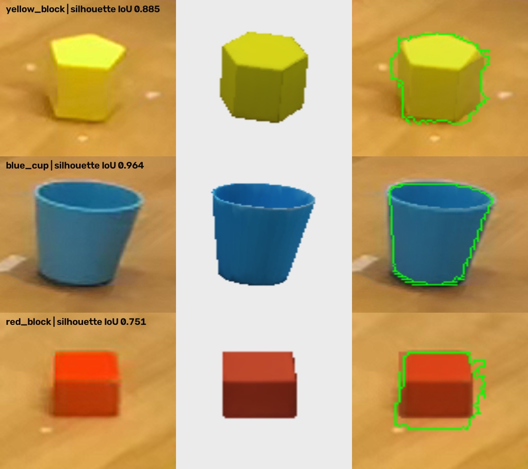
| Asset | Source-view silhouette IoU | Median stereo depth error |
|---|---|---|
| Yellow block | 0.885 | 0.6 mm |
| Blue cup | 0.964 | 0.7 mm |
| Red block | 0.751 | 3.7 mm |
These scores measure a source view used during alignment, so they are fit diagnostics rather than independent ground-truth accuracy.
How the 3D background is made
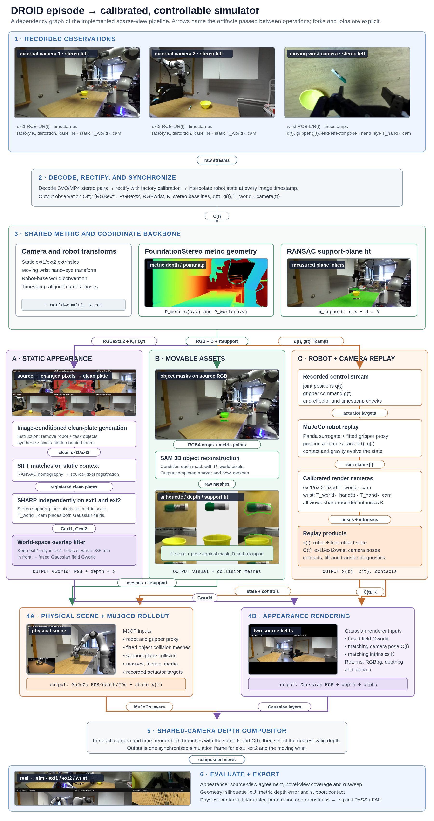
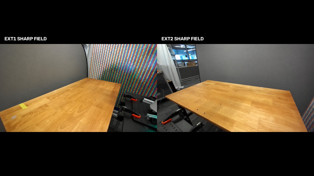
This is a calibrated fusion of two independently predicted SHARP fields. It uses both static external views, while avoiding a long per-scene 3DGS optimization.
- Choose two source images. Rectified left images from ext1 and ext2 frame 0 provide complementary room coverage. Their intrinsics and robot-frame extrinsics come from DROID and the ZED factory calibration.
- Complete both backgrounds. Image generation independently removes the robot and movable task objects from each view and fills newly exposed pixels. Filled pixels are inferred rather than observed.
- Register both completions. SIFT features, ratio matching, and RANSAC homographies align the generated images back to their untouched source landmarks.
- Initialize one Gaussian scene. Apple SHARP provides feed-forward seeds, which are then jointly optimized as one shared two-camera field against real RGB and stereo depth. Generated completion pixels are initialization-only and excluded from the observed-pixel loss.
- Recover metric scale and world pose. FoundationStereo depth and support-plane inliers independently scale each field. A point-to-plane ICP pass registers the ext2 metric cloud to ext1, refining its recorded pose by about 8.6° and 3.2 cm before both fields enter the shared MuJoCo world.
- Fuse and composite. Ext2 Gaussians already covered by ext1 are removed unless they fill a hole or lie materially in front. Exact ext1/ext2 comparisons use their source field; the wrist and free cameras use the fused field. MuJoCo geometry is depth-composited from the same camera pose.
gupta_background_sweep.mp4 moves a virtual camera through the fused two-view field. Ext2 now has its own reconstructed source field; black gaps and stretched texture remain possible where neither external camera observed the scene.Two additional DROID video tests
To test transfer beyond the original AUTOLab scene, the same ingestion and reconstruction stages were run on episodes from CLVR and GuptaLab. Both external cameras now contribute completed, calibrated, stereo-scaled SHARP fields. The wrist stream is synchronized for comparison and camera placement, while SAM 3D supplies movable-object geometry.
CLVR · bottle pick and return
CLVR+13759f6e+2023-05-19-21h-57m-01s · “Pick up the bottle and put it back down on the table.”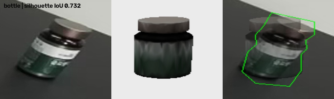
GuptaLab · marker into bowl
GuptaLab+553d1bd5+2023-04-20-14h-28m-44s · “Pick up the marker from the table and put it in the bowl.”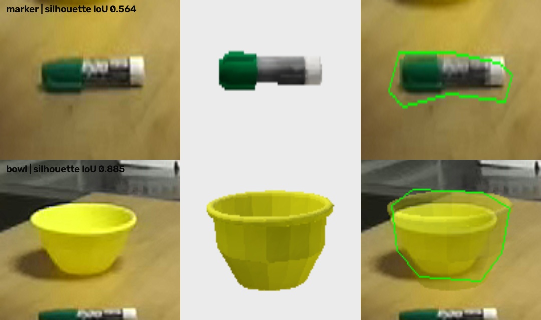
What is reconstructed, and what is assumed
The pipeline uses ext1 and ext2 frame 0 for Gaussian background appearance, with separate stereo scale fits and camera-to-robot transforms. The moving wrist camera is synchronized and calibrated, but its pixels are not fused into the static field. SAM 3D supplies completed object geometry, while stereo supplies metric scale and placement.
Download and reproduce
Download runnable MuJoCo scene (7 MB)
The package contains the portable MJCF, visual and collision assets, saved rollouts, validation reports, a small action-driven environment, licenses, and instructions. Model checkpoints and account credentials are excluded.
Public source: DROID episode AUTOLab+84bd5053+2023-08-17-17h-03m-46s. Task: “Get the yellow block from the table and place it in the blue cup.” Built September 2026.
End-to-end pipeline
This dependency graph follows the GuptaLab marker episode from synchronized observations to evaluation. It exposes the clean-plate removal and registration steps, the measured support plane, every branch input and output, and the two separate joins used for physical assembly and final rendering.